Ampeg Phazzer Clone
Last updated 01/17/23
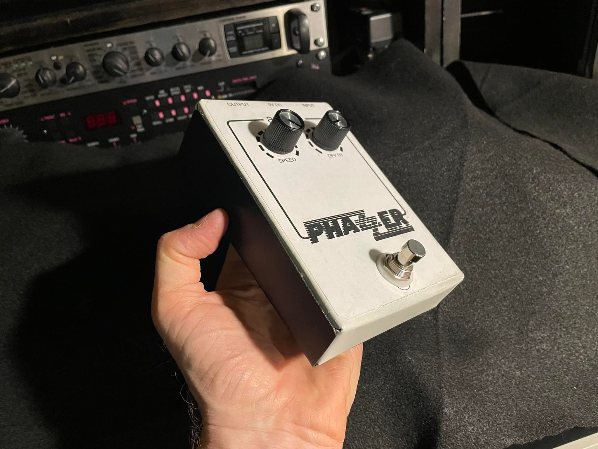
Until recently, I wasn't aware of the existence of this relatively unknown, great sounding phaser pedal made by Ampeg sometime in the 1970s. When I looked into it, there was a lot of chatter about it being no big deal and that is was basically an MXR Phase 90 using a CD4069 IC chip instead of the four matched FETs. When I saw the schematic, I thought that was a pretty clever solution to get around having to match FETs to get an optimally functioning circuit - the IC chip has them built into it by design. So of course, now I was intrigued by it and had to build it. One thing I decided immediately is that I wanted to have same enclosure design but to shrink it down as much as possible by making the enclosure smaller and also taking the factory PCB design and making it as small as I could get it. I also wanted to add a depth control, which took some experimentation but I eventually figured out how to add one.
Below are pictures and commentary of this project. I used an old thrift store cookie sheet to make the enclosure and that worked out pretty well!
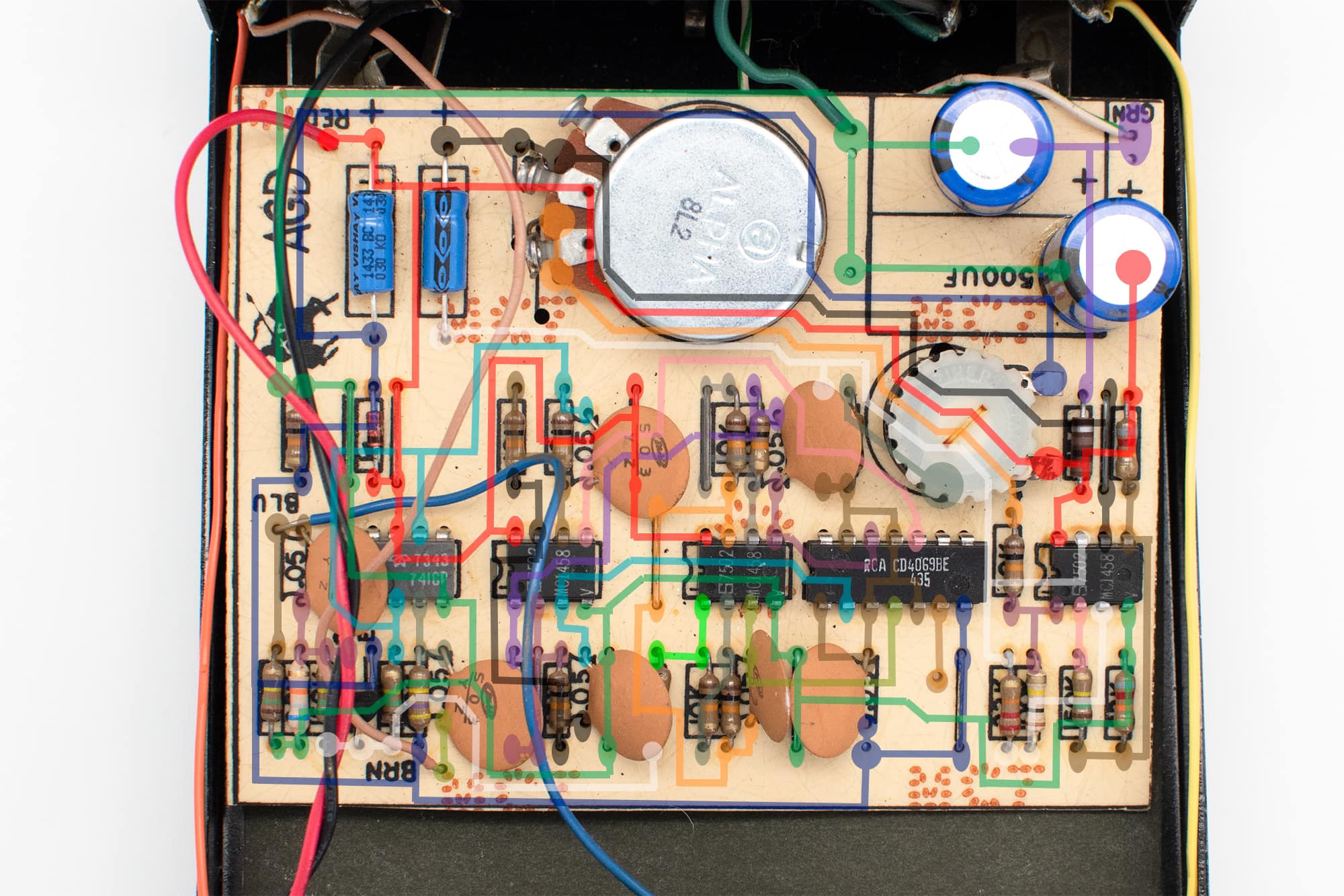 |
The first thing I did was to find an image of the original factory PCB so I could generate some AutoCAD drawings from which I could tweak into a little smaller version. Someone already identified where all the tracks on the PCB went so that made the whole process a little easier. |
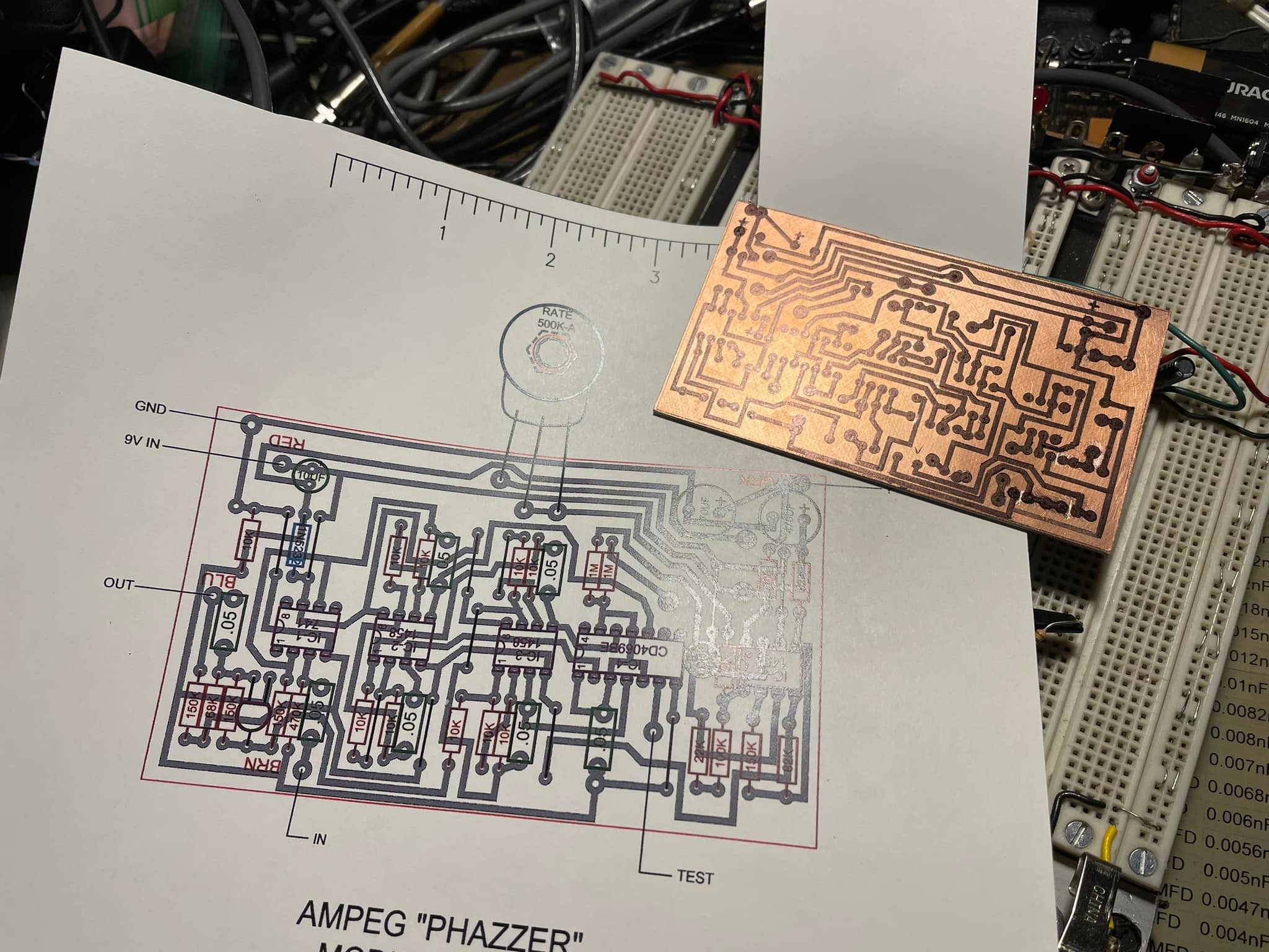 |
Here I have generated a PCB layout which I transferred to blank PCB, which I could then etch. |
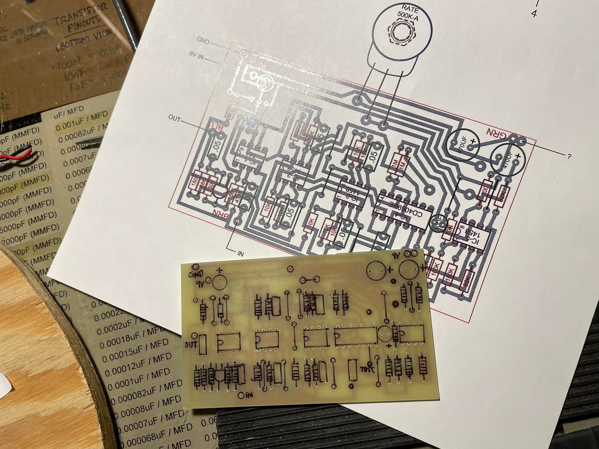 |
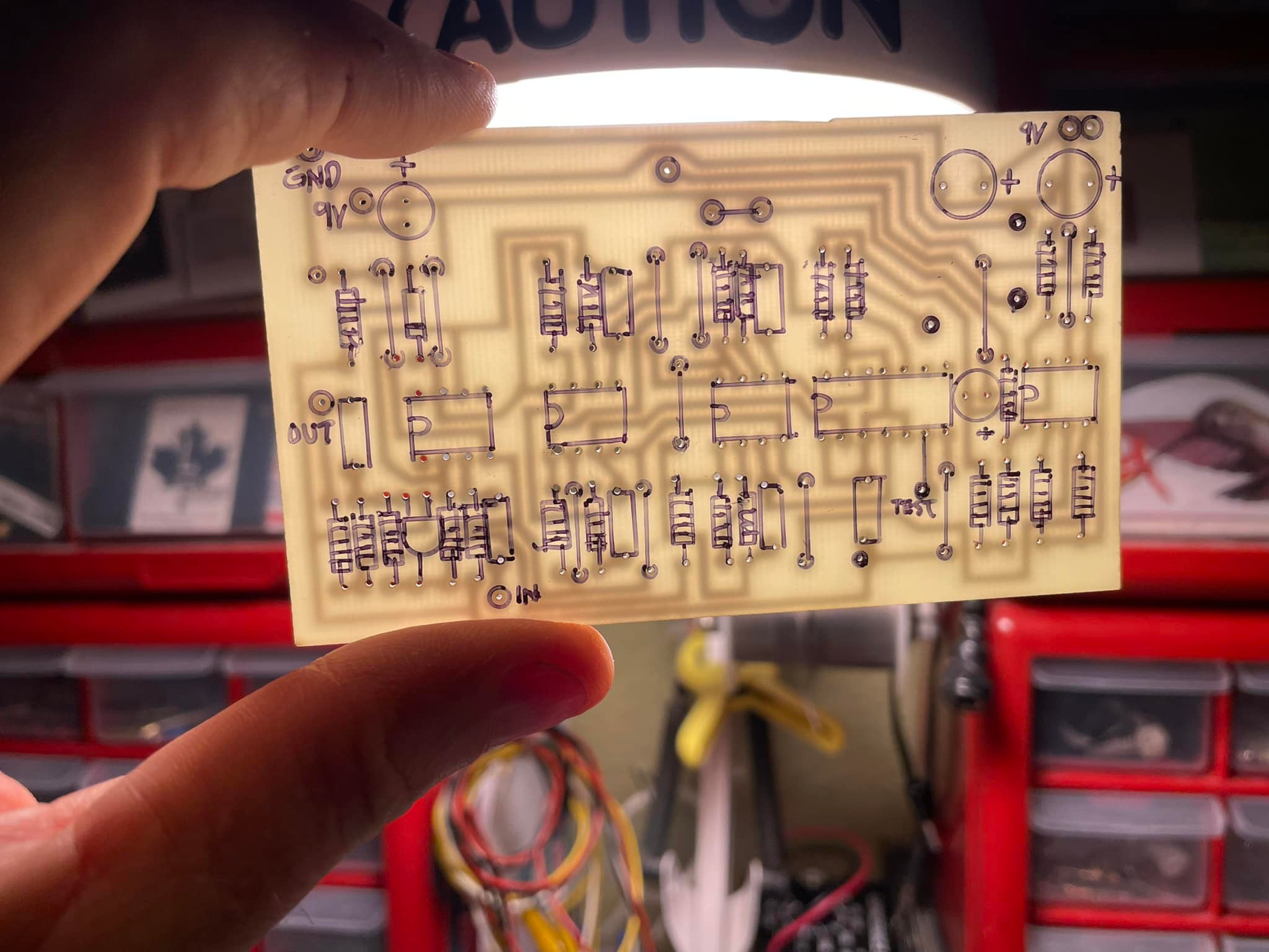
This is after etching and drilling. I did my customary Sharpie markup to identify where all the components go. I find doing this just makes things easier. |
 |
All ready for the components to get soldered on the board! |
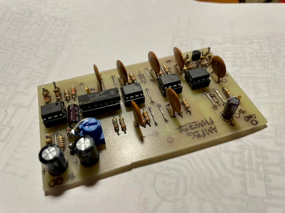 |
Everything soldered to the PCB and ready to be wired up. |
 |
The next thing I did was make a cardboard mockup. This allowed me to see how it would actually work in the real world. I wanted to add a depth control, which I found a way to do. This made it a two knob affair. |
 |
Satisfied that my shrunk down version of the original would work, it was time to move on to making the actual enclosure. |
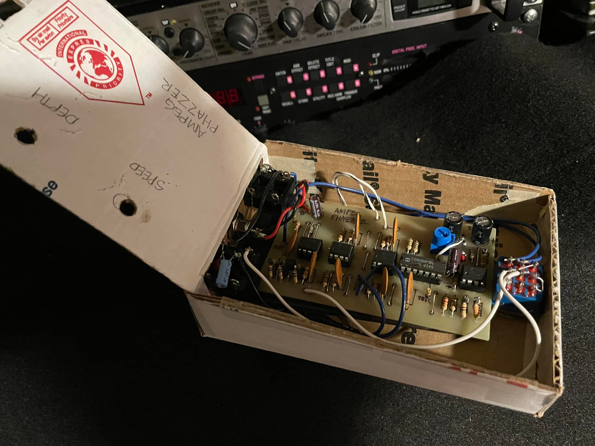 |
Here is a look "under the bonnet". Everything was fully functional at this point. |
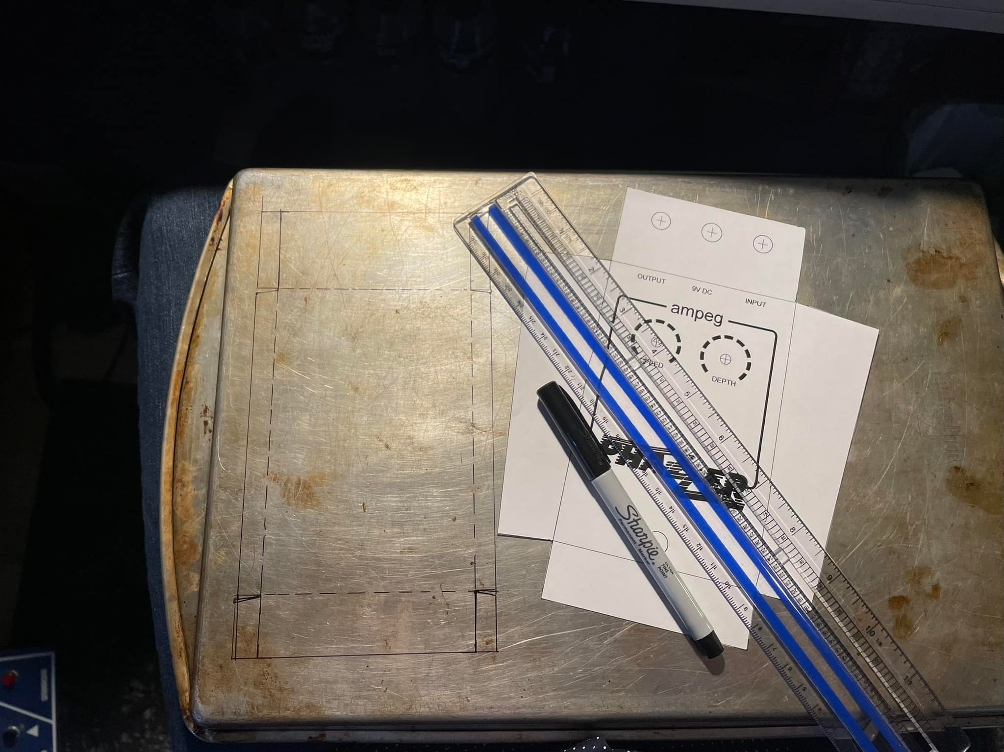 |
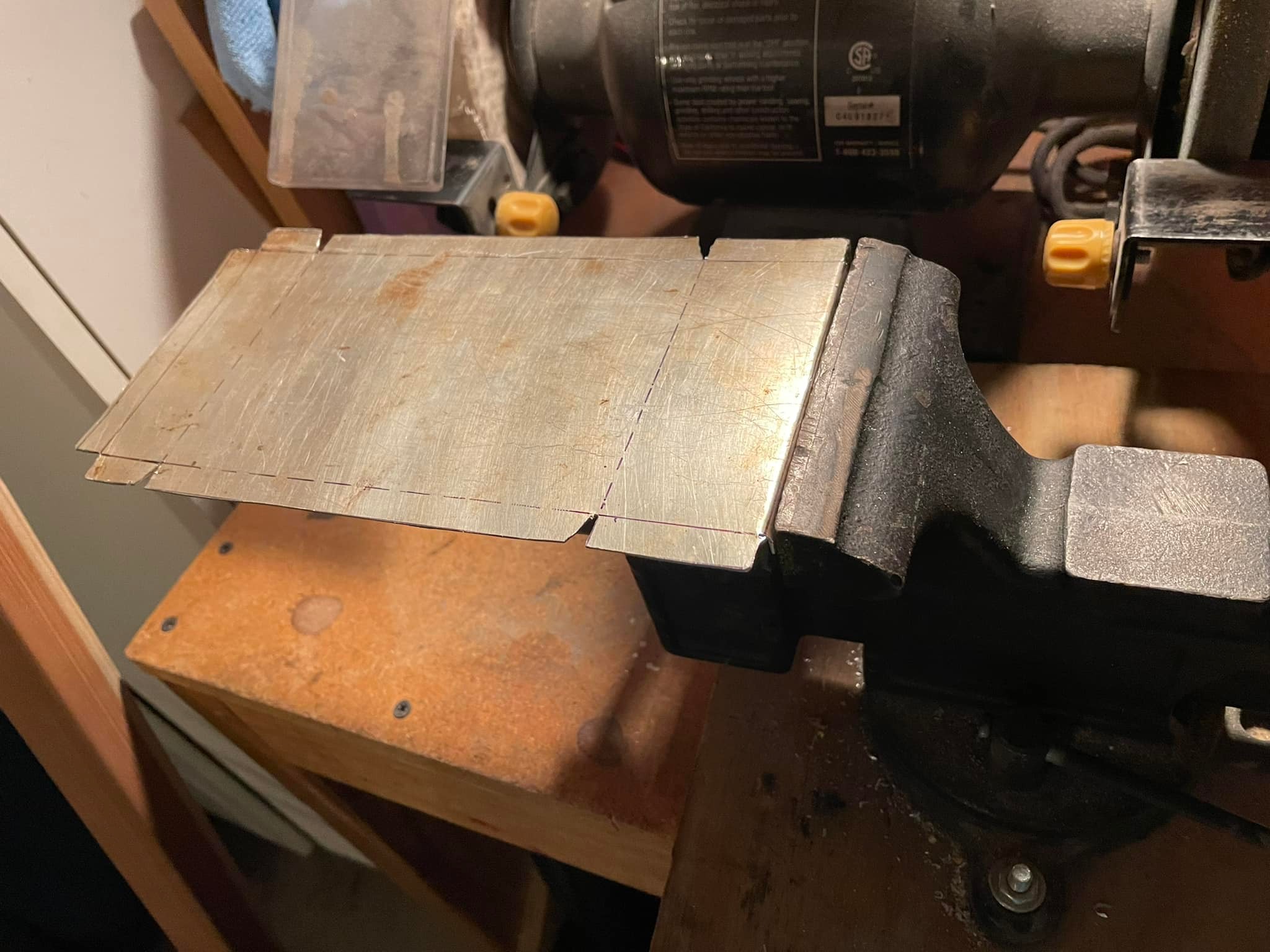
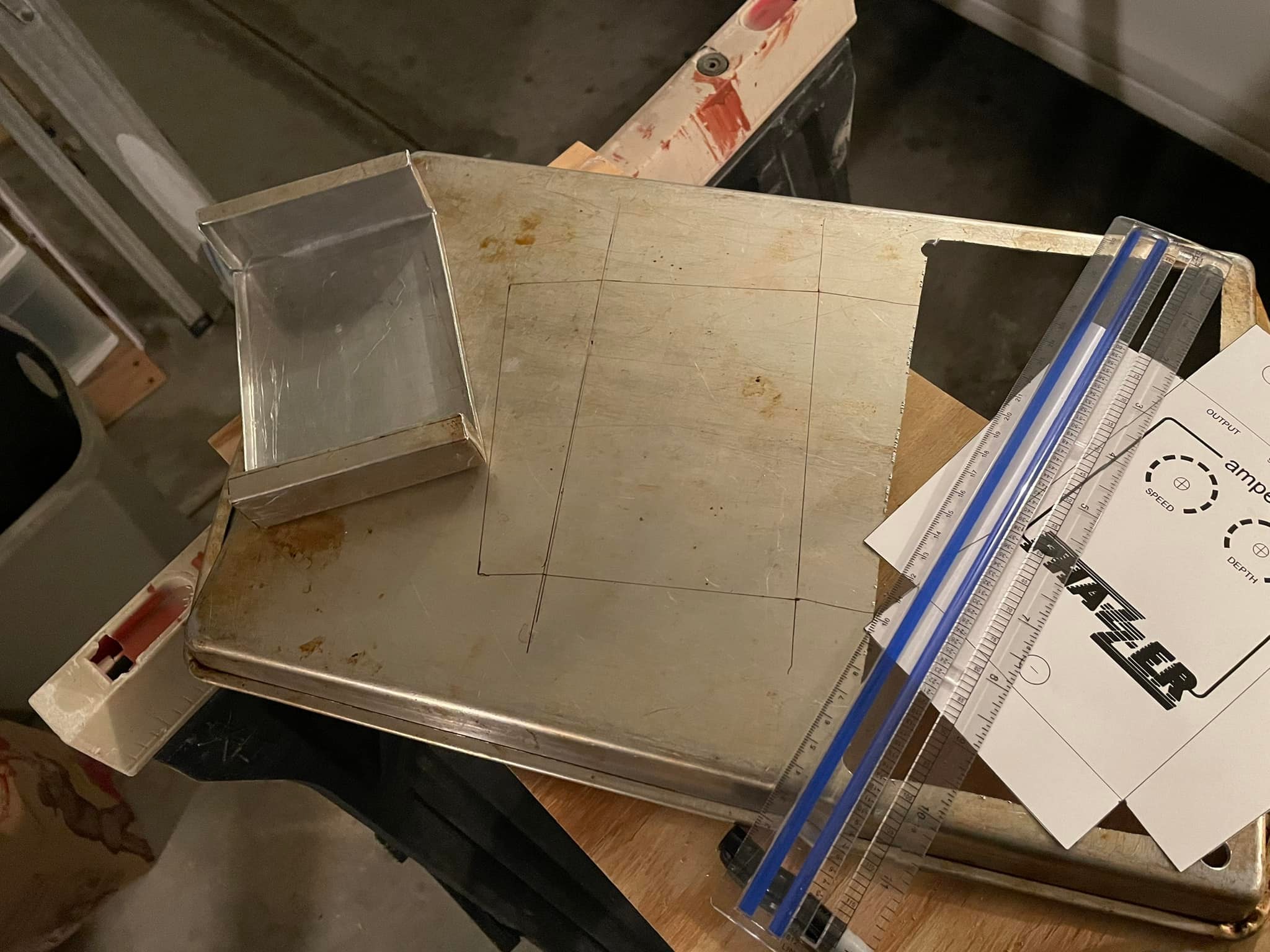
The next step was finding a suitable sized piece of metal from which to create my enclosure. The local thrift store had a nice old aluninum cookie sheet which was the perfect size. Here I am marking it up so I could cut it up. |
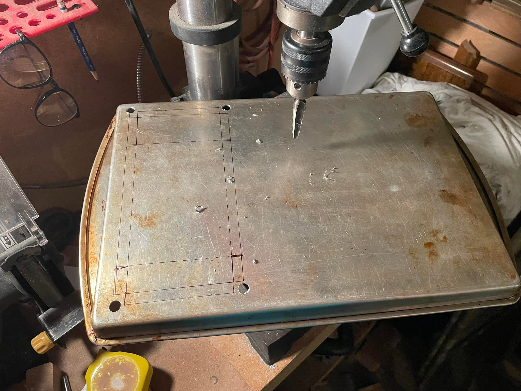 |
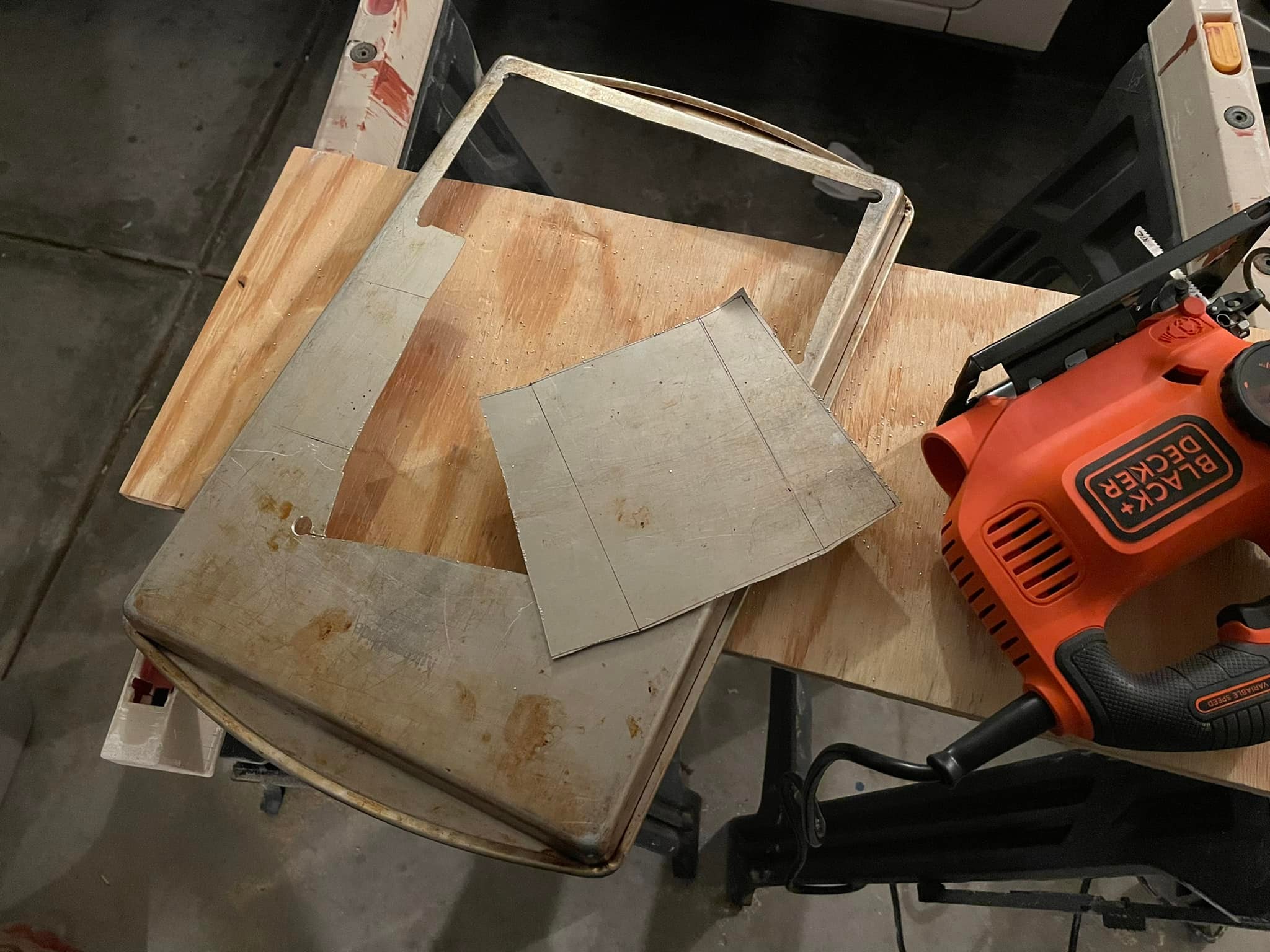
Drilling holes for the jigsaw blade to fit thru and to easily turn the corners. |
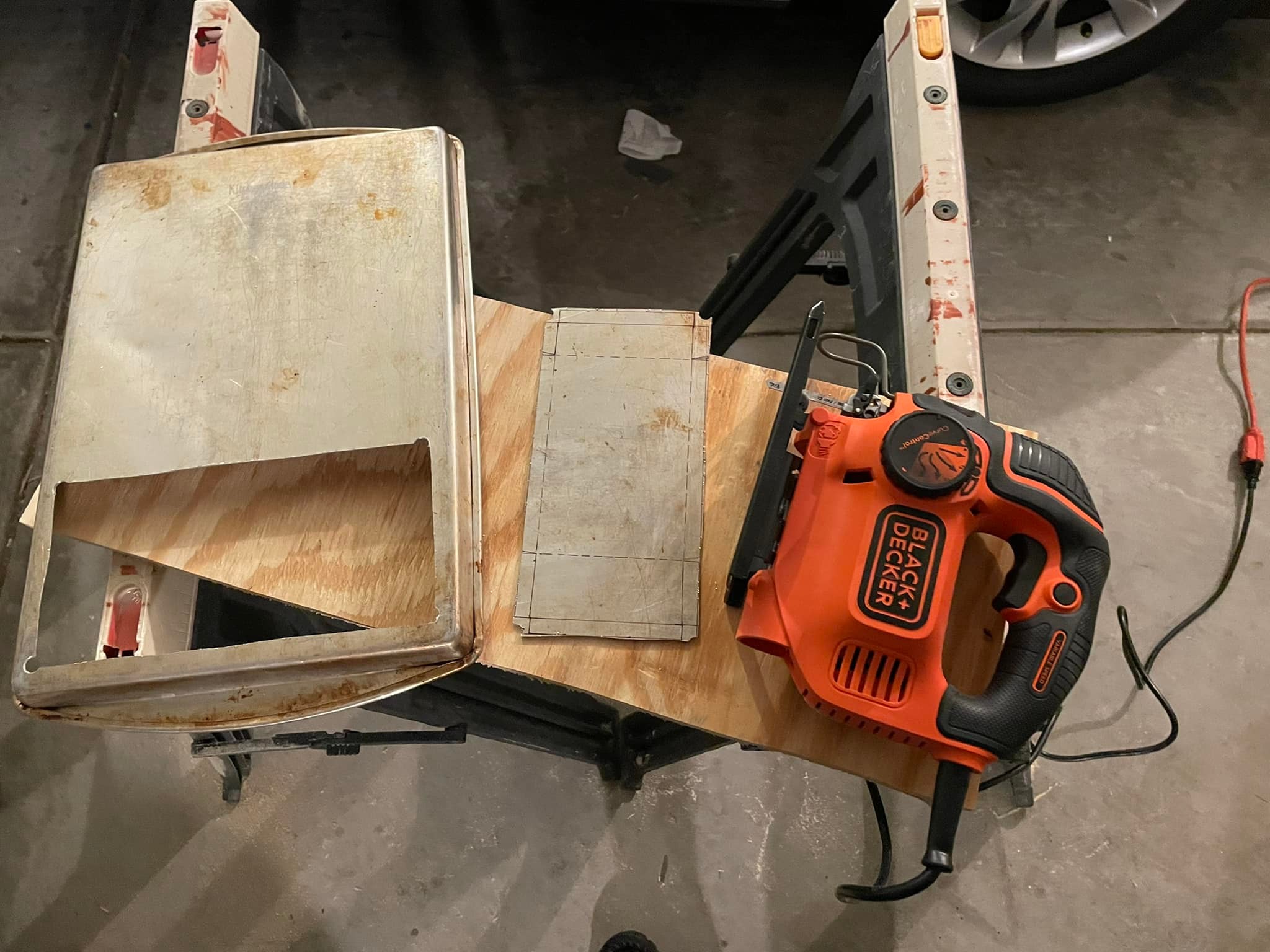 |
Now that the top piece cut out I had to figure out how I was going to make those bends. |
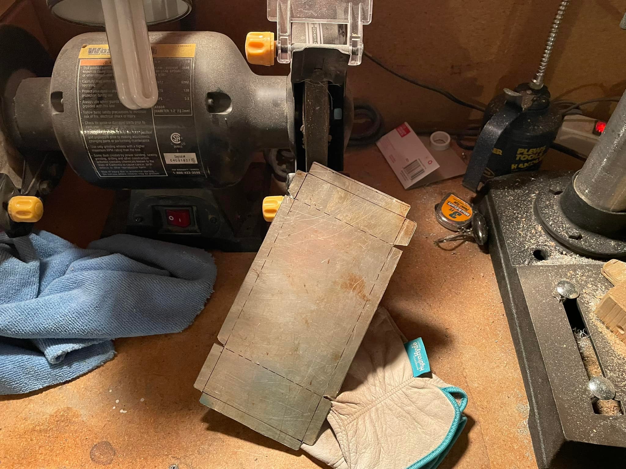 |
Since aluminum is very easy to work with, some of the smaller bends I was able to make simply using some pliers. |
 |
A vise worked great for making most of the bends. |
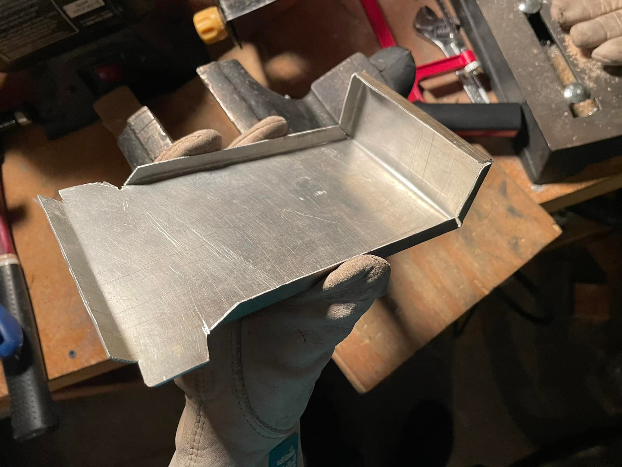 |
Almost there! |
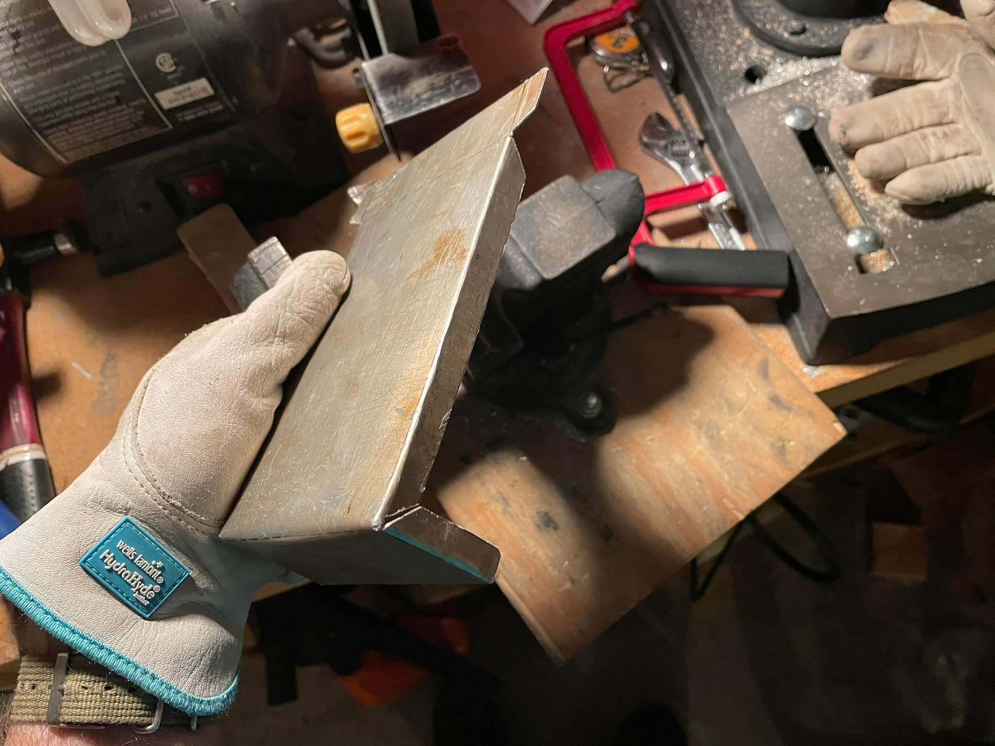 |
The last few bends were the trickiest ones to do. |
 |
Second to last set of bends! |
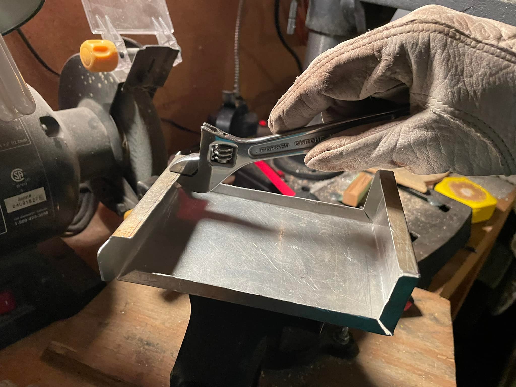 |
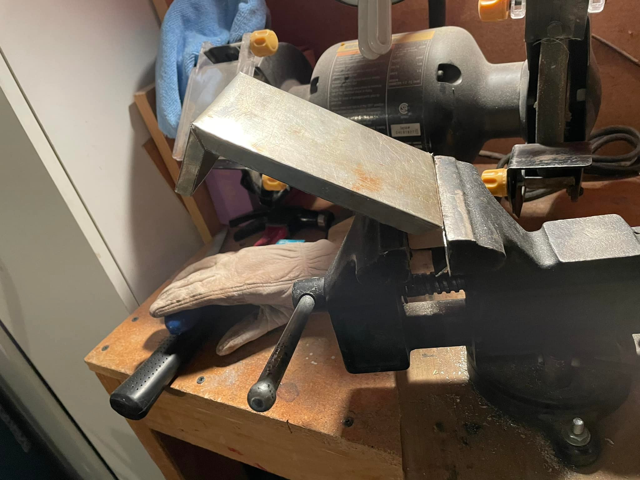
A small adjustable wrench helped me make the final three bends. |
 |
Time to do the simple piece, the bottom. |
 |
Only two bends required on this piece! |
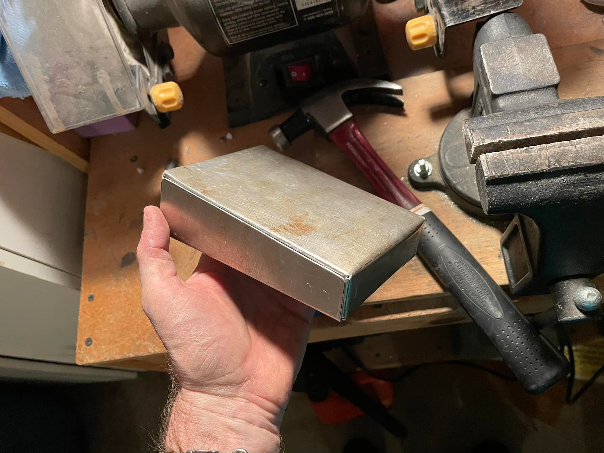 |
It turned out pretty well considering how I created it. |
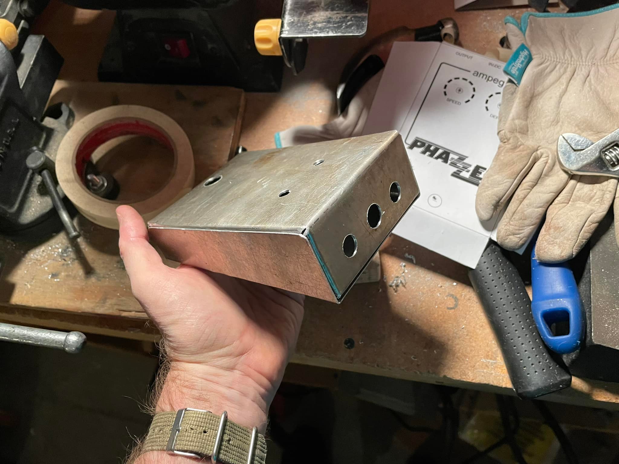 |
Holes drilled! |
 |
I like using cardboard mockups sometimes, it makes the R&D process a lot easier. |
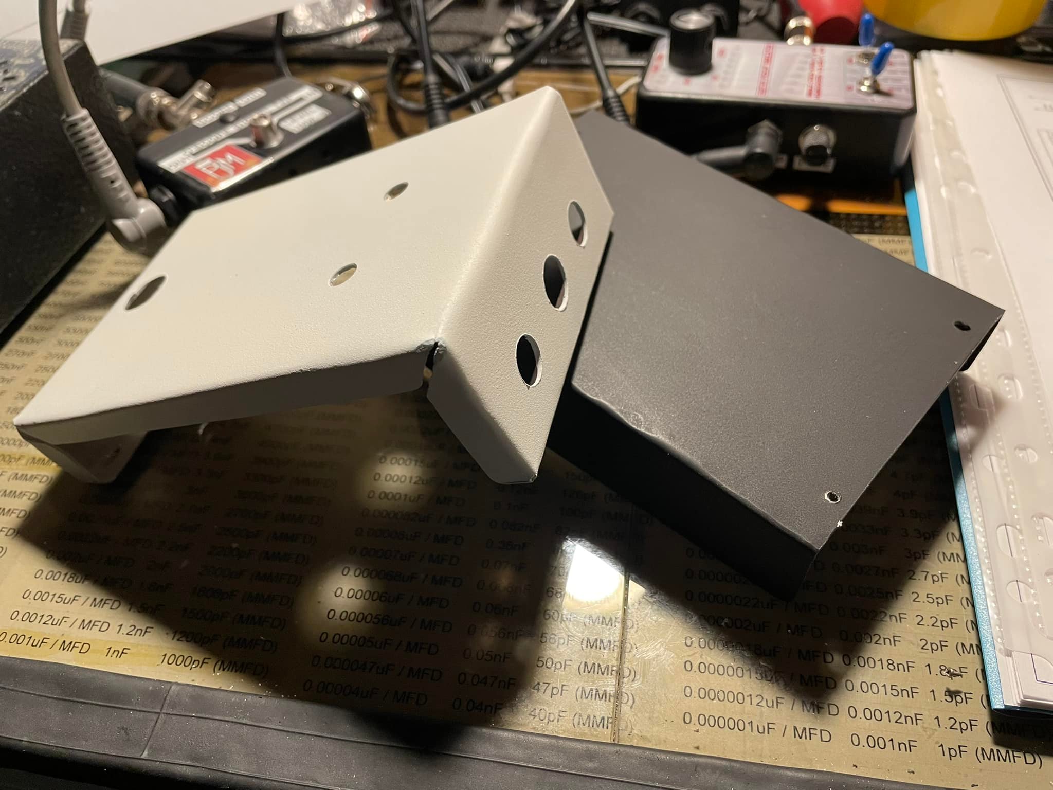 |
Top and bottom pieces painted. I went with a reverse color scheme because I don't have a good way to do white graphics on a black background. |
 |
Graphics applied. Also made using AutoCAD. |
 |
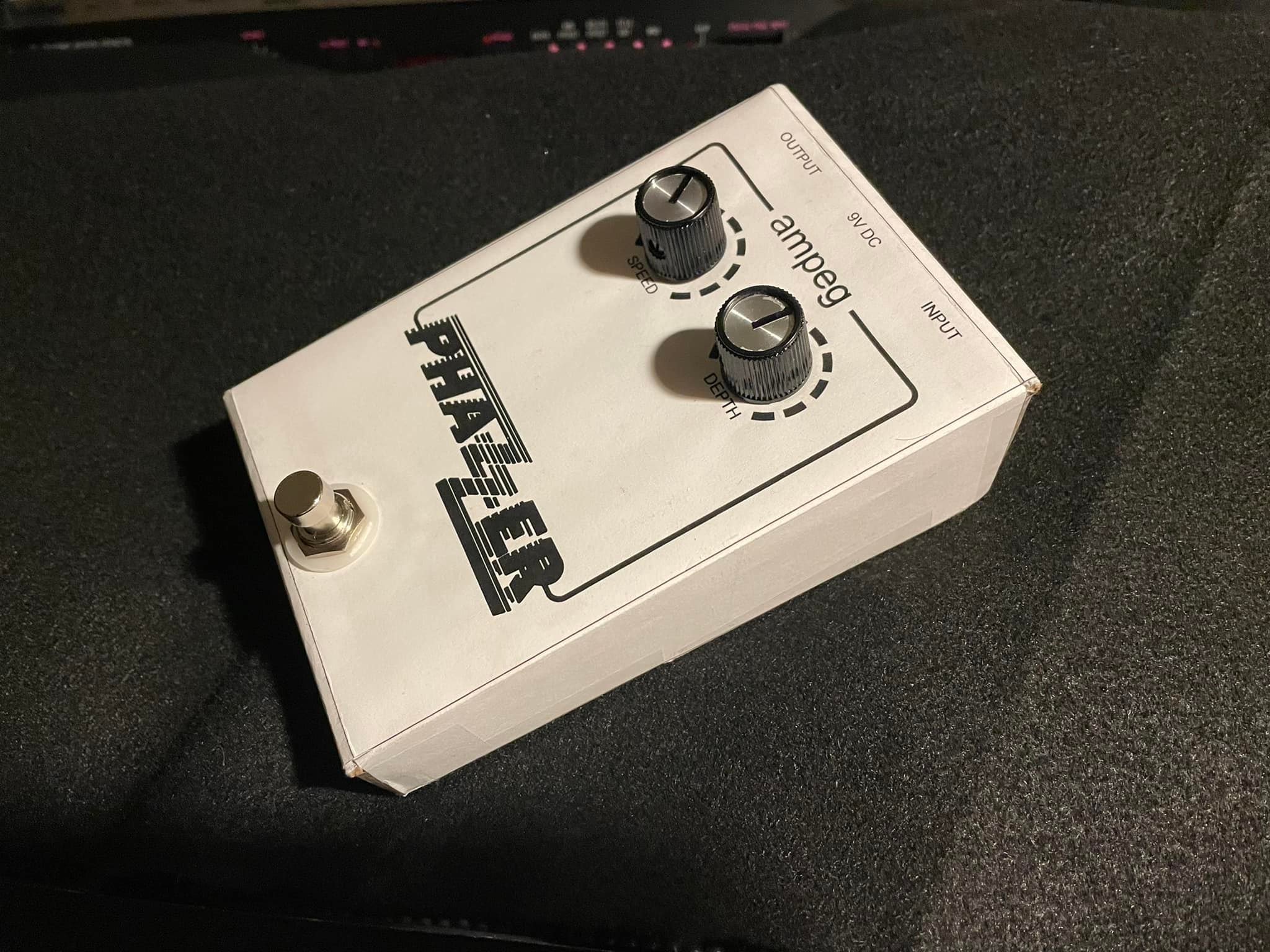
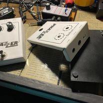
Everything has been transferred from the cardboard mockup to the official enclosure. |
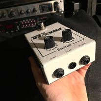 |
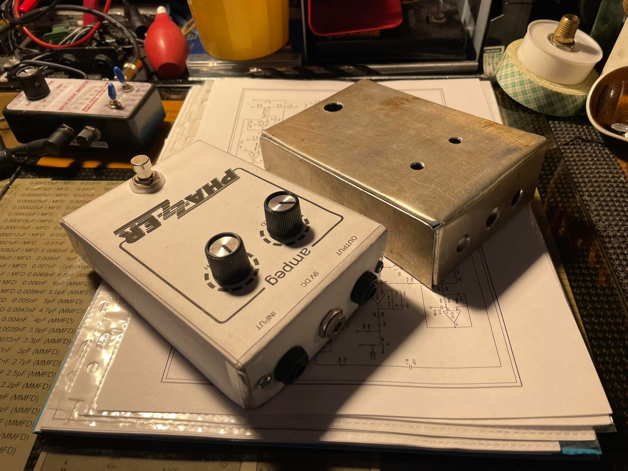
I like the size of my unit. The original seems so huge in comparison. |
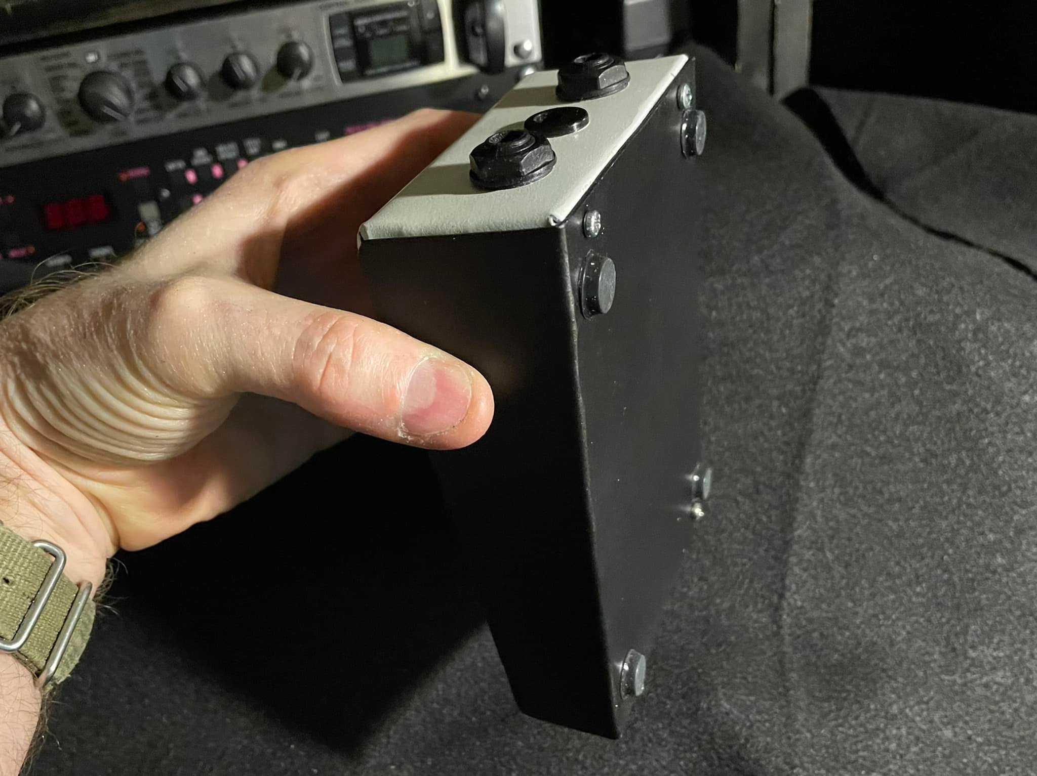 |
Not much to see here... just some rubber feet on the four corners. |
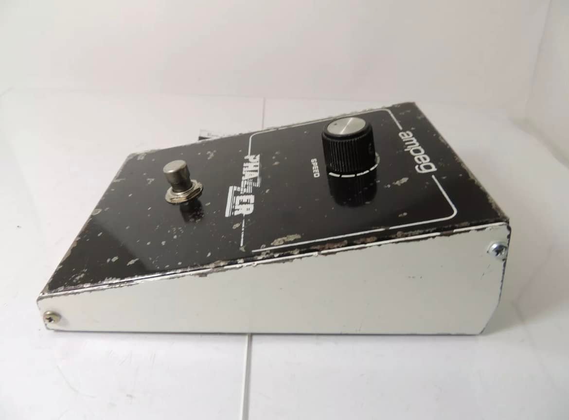 |
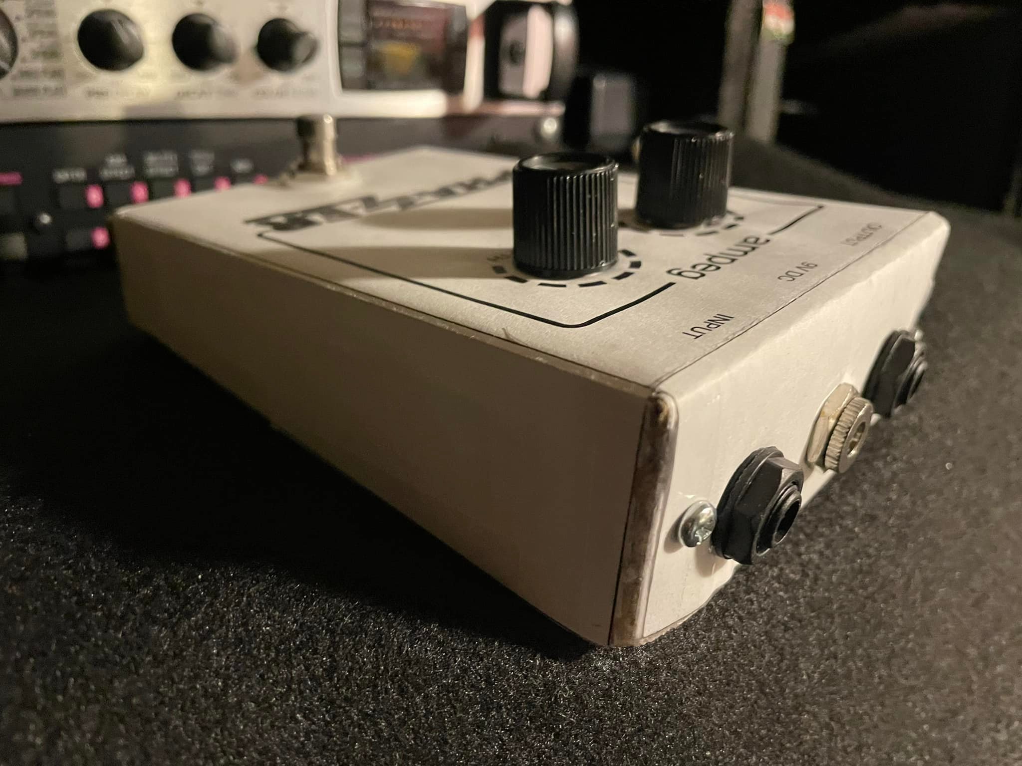
Here is side profile of an actual Ampeg Phazzer. |